
Altitude Control & Dynamics Sensor Card
Published:
Nucleus Altitude ControlDynamics Sensor Card
Theory of Operation
Main Processor
Communication and Control Interfaces
Altitude Control System
This subsystem contains the systems required to control the ballast portion of altitude control.
Dynamics Sensors
This subsystem is primarily a set of interfaces off the card to sensor nodes located throughout the HAB. The goal is to collect data from multiple points to create a model of the vehicle during flight. This will assist in validating movementmotion models and inform decisions for future attitude control systems.
Power Management
Electrical Implementation
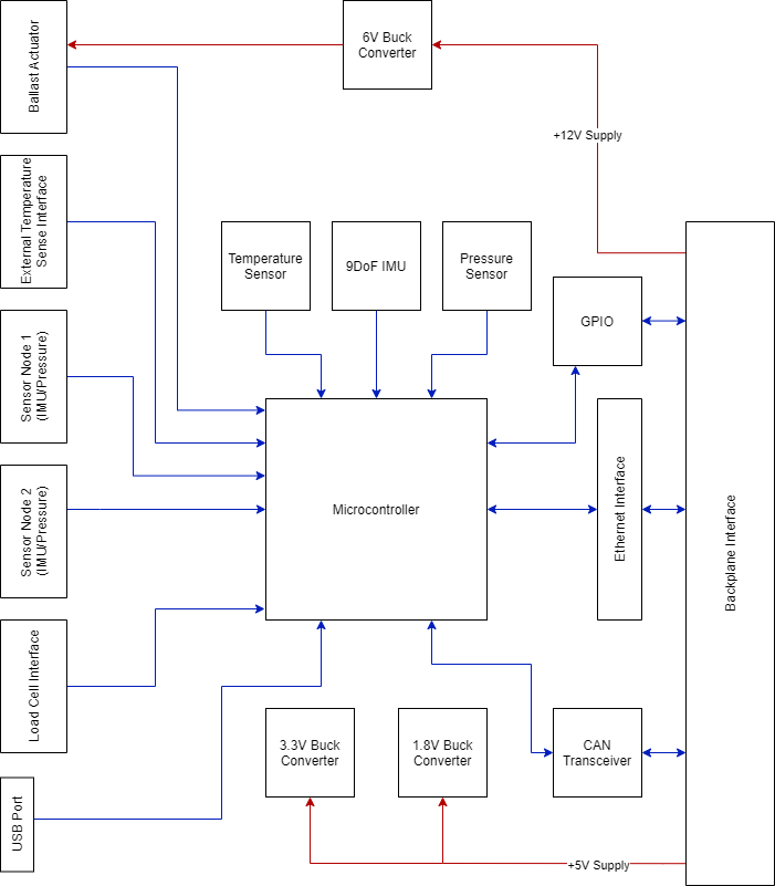
Note Red represents power and blue represents data signals
Major components
Microcontroller - STM32F407VET6TR
CAN Transceiver - TCAN1051
Pressure Sensor - BMP388
9 DoF IMU - ICM-20948
Temperature Sensor - TMP117A
Ethernet PHY - KSZ8081MNX
Voltagecurrent monitor - INA3221
Power Supplies
A list of devices per rail is provided below, as well as expected current requirements based on a power analysis of the hardware stack. The detailed analysis is available through the following google sheets link:
Hardware Stack Power Analyses
12V Power Rail
- 6V Switching Regulator
- E-Fuse
405mA current draw
6V Power Rail
- Servo Channels
- Motor Channels
764mA current draw
5V Power Rail
- 3.3V Switching Regulator
- 1.8V Switching Regulator
- E-Fuse
73mA current draw
3.3V Power Rail
- CAN Transceiver
- Ethernet Transceiver
- Microcontroller
- ADC
- Temperature Sensor
89mA current draw
1.8V Power Rail
- IMU
- Pressure Sensor
4.5mA current draw
Power Considerations
Per the power analysis, it is expected that the Altitude ControlDynamics Card will draw approximately 1007 mW of power during nominal operation. This analysis also includes 125mA current flowing through each motor channel and 250mA through each of the servo channels. These are initial estimates and will be updated during further documentation review and board testing
Design Implementation
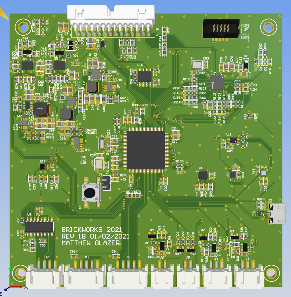
Connectors
Backplane
There is one 28 pin Molex MilliGrid shrouded right angle connector providing all interfaces to and from the Avionics Sensor Card to the Backplane and Main Flight Computer.
Molex Part # 0878332820
| 1 | 3 | 5 | 7 | 9 | 11 | 13 | 15 | 17 | 19 | 21 | 23 | 25 | 27 | 29 | 31 | 33 |
| 2 | 4 | 6 | 8 | 10 | 12 | 14 | 16 | 18 | 20 | 22 | 24 | 26 | 28 | 30 | 32 | 34 |
Reference view for pinout of connector is from top edge of board looking towards backplane connector.
| Pin Number | Pin Function |
|---|---|
| 1 | 12V Power Rail |
| 2 | 12V Power Rail |
| 3 | Ground |
| 4 | Ground |
| 5 | 5V Power Rail |
| 6 | 5V Power Rail |
| 7 | Ground |
| 8 | Ground |
| 9 | CAN + |
| 10 | CAN - |
| 11 | Ground |
| 12 | Ground |
| 13 | GPIO - Common |
| 14 | GPIO - 4 |
| 15 | GPIO - 5 |
| 16 | GPIO - 6 |
| 17 | SPARE |
| 18 | SPARE |
| 19 | SPARE |
| 20 | SPARE |
| 21 | SPARE |
| 22 | SPARE |
| 23 | Ground |
| 24 | Ground |
| 25 | Ethernet Link 2 - TX+ |
| 26 | Ethernet Link 2 - TX- |
| 27 | Ethernet Link 2 - RX+ |
| 28 | Ethernet Link 2 - RX- |