
Backplane
Published:
Nucleus : Backplane Interface Board
Theory of Operation
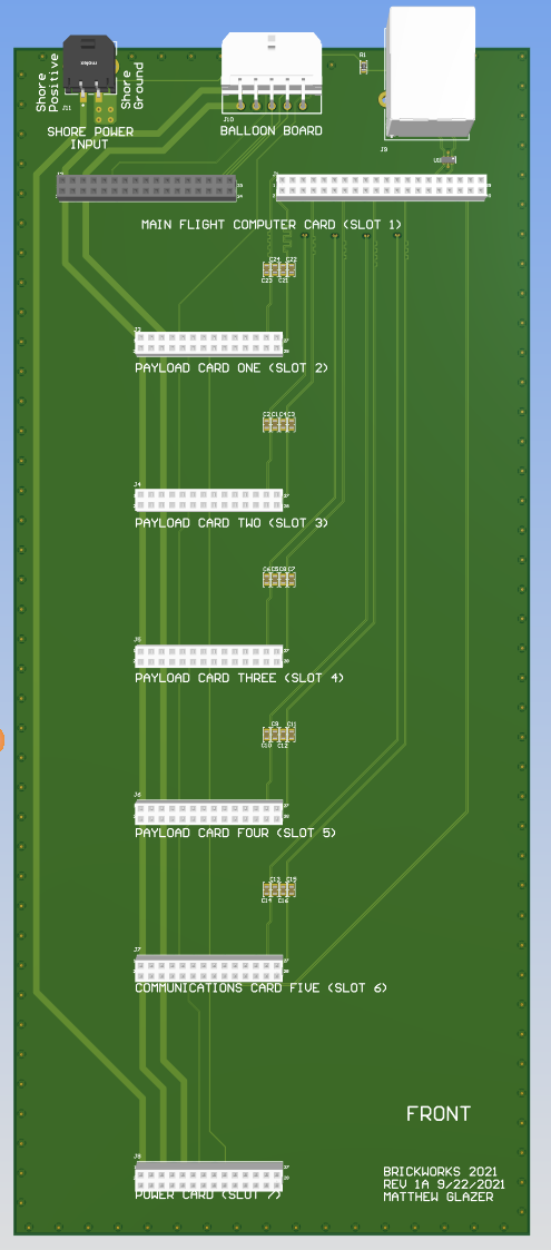
The Backplane acts as the interconnect between all of the various payload cards, providing power and data connections throughout. Slot one is dedicated to the Main Flight Computer, slot seven is dedicated to the Power card. Slot six is notionally dedicated to the Communications card as it has an additional USB interface routed to it but can be used for any generic payload card as it follows the implementation of slots two through five.
Electrical Interface

Major components
ESD - TPD4S010DQAR
Power Supplies
There are no power supplies implemented on the backplane, it is purely pass through for power rails and data lines.
Power Considerations
The backplane dissipates no discernible amounts of power.
Design Implementation
The Backplane is implemented as a four-layer PCB, following the stack-up provided from Macrofab as a starting point (Macrofab stackup). Copper weight is 1 oz, also following dimensions per the Macrofab stackup. Board dimensions are 100mm x 230mm, as dictated by the width of the payload cards and the required height to support a seven card configuration.
There are three differential pair implementations on the Backplane: 120 ohm, 100 ohm and 90 ohm differential pairs for the CAN bus, Ethernet and USB routing; respectively. These were configured through Altium using built-in tools than take stackup layer values such as copper weight, base material and board thickness as input and generate the required trace width and separation values to maintain the proper differential pair impedance.
Ground pours are used on the second and third layers of the PCB, these include a solid ground plane located on layer two and additional ground planes on layer three. Care was taken to make sure any differential routing had solid ground planes under the routing to maintain signal integrity.
Four different communication interfaces are implemented as interconnects between the payload cards. Each interface is described in its own subsection. Power is routed from the shore power input directly to the Power card connector and the 5V and 12V rails generated from said card are then routed to each other payload card interface on the backplane.
Ethernet
Ethernet is routed from J1 on the Backplane to the respective cards that accept ethernet connections (J2 through J6). The capacitive coupling is located on the Backplane and the capacitors are placed near the connector associated with the specific ethernet connection. The trace routing follows 100 ohm differential pair routing. Trace lengths were tuned for both RX and TX pair lengths as well as for the individual pairs.
CAN
CAN is routed from J2 through J10 and back through each payload card interface sequentially, effectively a linear line between the payload card slots. The trace routing follows 120 ohm differential pair routing. Termination for the CAN network is on the MFC and Power cards so the network starts at the MFC and ends at the Power card.
USB
There is a single USB link routed from J2 to J7 for the Communications card. The trace routing follows 90 ohm differential pair routing.
GPIO
GPIO traces are routed in their respective groups of three for the discrete GPIOs and a single trace for the common GPIO. Traces were routed on the fourth layer of the board so to not interfere with other signals that require impedance matching.
Power
Power from the Shore Power connector is routed to the Power card connector. This trace is a 1.25mm wide trace capable of 2.8A, which at 24V for the input supply is expected to more than sufficient for required power needs while on the ground.
Routing from the Power card to other payload cards is also done through 1.25mm traces. As current expected max loading for the 5V supply is ~1A and ~2A for the 12V supply, both have additional margin for future uses and adding capabilities. To note, the 2A on the 12V supply includes pulse applications.
Design Implementation
Connectors
One 40 pin Molex MilliGrid vertical receptacle, one 34 pin Molex MilliGrid vertical receptacle and six 28 pin Molex MilliGrid vertical receptacles provide the interfaces between the various payload cards. There is also a Molex Microfit header and RJ45 connector for ground station interface and a 10 pin molex minifit header for connection to the balloon board.
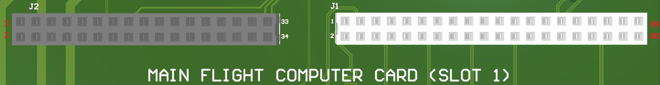
Main Flight Computer Interface (Slot 1)
Molex Part #: 0791077016
Power/GPIO Interface
| 1 | 3 | 5 | 7 | 9 | 11 | 13 | 15 | 17 | 19 | 21 | 23 | 25 | 27 | 29 | 31 | 33 |
| 2 | 4 | 6 | 8 | 10 | 12 | 14 | 16 | 18 | 20 | 22 | 24 | 26 | 28 | 30 | 32 | 34 |
Reference view for pinout of connector is from FRONT of card, Power/GPIO interface is J2.
Pin Number
Pin Function
| Pin Number | Pin Function |
|---|---|
| 1 | 12V Power Rail |
| 2 | 12V Power Rail |
| 3 | Ground |
| 4 | Ground |
| 5 | 5V Power Rail |
| 6 | 5V Power Rail |
| 7 | Ground |
| 8 | Ground |
| 9 | CAN + |
| 10 | CAN - |
| 11 | Ground |
| 12 | Ground |
| 13 | GPIO - Common |
| 14 | GPIO - 1 |
| 15 | GPIO - 2 |
| 16 | GPIO - 3 |
| 17 | GPIO - 4 |
| 18 | GPIO - 5 |
| 19 | GPIO - 6 |
| 20 | GPIO - 7 |
| 21 | GPIO - 8 |
| 22 | GPIO - 9 |
| 23 | GPIO - 10 |
| 24 | GPIO - 11 |
| 25 | GPIO - 12 |
| 26 | GPIO - 13 |
| 27 | GPIO - 14 |
| 28 | GPIO - 15 |
| 29 | GPIO - 16 |
| 30 | GPIO - 17 |
| 31 | GPIO - 18 |
| 32 | GPIO - 19 |
| 33 | GPIO - 20 |
| 34 | SPARE |
Molex Part #: 0791077019
Ethernet Interface
| 1 | 3 | 5 | 7 | 9 | 11 | 13 | 15 | 17 | 19 | 21 | 23 | 25 | 27 | 29 | 31 | 33 | 35 | 37 | 39 |
| 2 | 4 | 6 | 8 | 10 | 12 | 14 | 16 | 18 | 20 | 22 | 24 | 26 | 28 | 30 | 32 | 34 | 36 | 38 | 40 |
Reference view for pinout of connector is from FRONT of card, Ethernet interface is J1.
Pin Number
Pin Function
| Pin Number | Pin Function |
|---|---|
| 1 | Ethernet Link 2 - RX+ |
| 2 | Ethernet Link 2 - RX- |
| 3 | Ethernet Link 2 - TX+ |
| 4 | Ethernet Link 2 - TX- |
| 5 | Ground |
| 6 | Ground |
| 7 | Ethernet Link 3 - RX+ |
| 8 | Ethernet Link 3 - RX- |
| 9 | Ethernet Link 3 - TX+ |
| 10 | Ethernet Link 3 - TX- |
| 11 | Ground |
| 12 | Ground |
| 13 | Ethernet Link 4 - RX+ |
| 14 | Ethernet Link 4 - RX- |
| 15 | Ethernet Link 4 - TX+ |
| 16 | Ethernet Link 4 - TX- |
| 17 | Ground |
| 18 | Ground |
| 19 | Ethernet Link 5 - RX+ |
| 20 | Ethernet Link 5 - RX- |
| 21 | Ethernet Link 5 - TX+ |
| 22 | Ethernet Link 5 - TX- |
| 23 | Ground |
| 24 | Ground |
| 25 | Ethernet Link 6 - RX+ |
| 26 | Ethernet Link 6 - RX- |
| 27 | Ethernet Link 6 - TX+ |
| 28 | Ethernet Link 6 - TX- |
| 29 | Ground |
| 30 | Ground |
| 31 | Ethernet Link 1 - RX+ |
| 32 | Ethernet Link 1 - RX- |
| 33 | Ethernet Link 1 - TX+ |
| 34 | Ethernet Link 1 - TX- |
| 35 | Ground |
| 36 | Ground |
| 37 | USB 2.0 - D- |
| 38 | USB 2.0 - D+ |
| 39 | SPARE |
| 40 | SPARE |
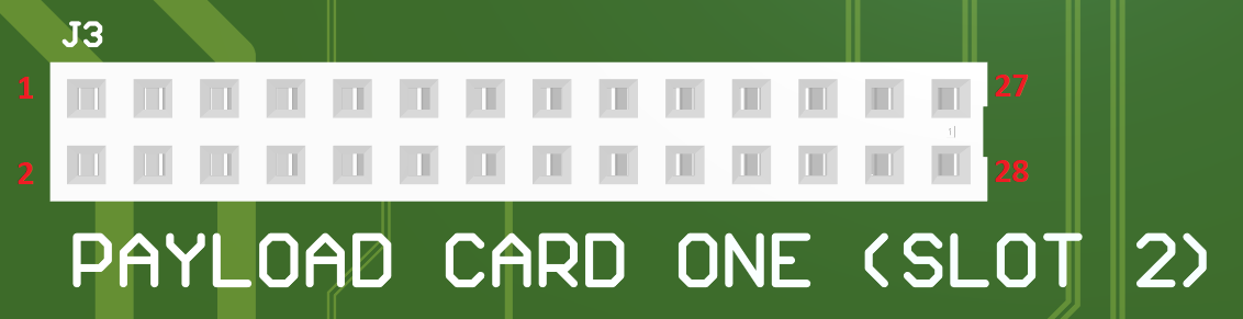
Payload Card Slot One (Slot 2)
Molex Part #: 0791077013
| 1 | 3 | 5 | 7 | 9 | 11 | 13 | 15 | 17 | 19 | 21 | 23 | 25 | 27 |
| 2 | 4 | 6 | 8 | 10 | 12 | 14 | 16 | 18 | 20 | 22 | 24 | 26 | 28 |
Reference view for pinout of connector is from FRONT of card.
Pin Number
Pin Function
| Pin Number | Pin Function |
|---|---|
| 1 | 12V Power Rail |
| 2 | 12V Power Rail |
| 3 | Ground |
| 4 | Ground |
| 5 | 5V Power Rail |
| 6 | 5V Power Rail |
| 7 | Ground |
| 8 | Ground |
| 9 | CAN + |
| 10 | CAN - |
| 11 | Ground |
| 12 | Ground |
| 13 | GPIO - Common |
| 14 | GPIO - 1 |
| 15 | GPIO - 2 |
| 16 | GPIO - 3 |
| 17 | SPARE |
| 18 | SPARE |
| 19 | SPARE |
| 20 | SPARE |
| 21 | SPARE |
| 22 | SPARE |
| 23 | Ground |
| 24 | Ground |
| 25 | Ethernet Link 2 - TX+ |
| 26 | Ethernet Link 2 - TX- |
| 27 | Ethernet Link 2 - RX+ |
| 28 | Ethernet Link 2 - RX- |
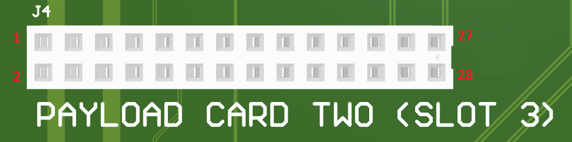
Payload Card Slot Two (Slot 3)
Molex Part #: 0791077013
| 1 | 3 | 5 | 7 | 9 | 11 | 13 | 15 | 17 | 19 | 21 | 23 | 25 | 27 |
| 2 | 4 | 6 | 8 | 10 | 12 | 14 | 16 | 18 | 20 | 22 | 24 | 26 | 28 |
Reference view for pinout of connector is from FRONT of card.
Pin Number
Pin Function
| Pin Number | Pin Function |
|---|---|
| 1 | 12V Power Rail |
| 2 | 12V Power Rail |
| 3 | Ground |
| 4 | Ground |
| 5 | 5V Power Rail |
| 6 | 5V Power Rail |
| 7 | Ground |
| 8 | Ground |
| 9 | CAN + |
| 10 | CAN - |
| 11 | Ground |
| 12 | Ground |
| 13 | GPIO - Common |
| 14 | GPIO - 4 |
| 15 | GPIO - 5 |
| 16 | GPIO - 6 |
| 17 | SPARE |
| 18 | SPARE |
| 19 | SPARE |
| 20 | SPARE |
| 21 | SPARE |
| 22 | SPARE |
| 23 | Ground |
| 24 | Ground |
| 25 | Ethernet Link 3 - TX+ |
| 26 | Ethernet Link 3 - TX- |
| 27 | Ethernet Link 3 - RX+ |
| 28 | Ethernet Link 3 - RX- |
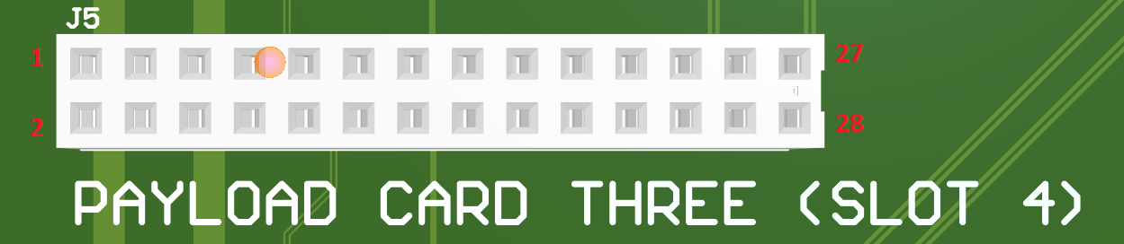
Payload Card Slot Three (Slot 4)
Molex Part #: 0791077013
| 1 | 3 | 5 | 7 | 9 | 11 | 13 | 15 | 17 | 19 | 21 | 23 | 25 | 27 |
| 2 | 4 | 6 | 8 | 10 | 12 | 14 | 16 | 18 | 20 | 22 | 24 | 26 | 28 |
Reference view for pinout of connector is from FRONT of card.
Pin Number
Pin Function
| Pin Number | Pin Function |
|---|---|
| 1 | 12V Power Rail |
| 2 | 12V Power Rail |
| 3 | Ground |
| 4 | Ground |
| 5 | 5V Power Rail |
| 6 | 5V Power Rail |
| 7 | Ground |
| 8 | Ground |
| 9 | CAN + |
| 10 | CAN - |
| 11 | Ground |
| 12 | Ground |
| 13 | GPIO - Common |
| 14 | GPIO - 7 |
| 15 | GPIO - 8 |
| 16 | GPIO - 9 |
| 17 | SPARE |
| 18 | SPARE |
| 19 | SPARE |
| 20 | SPARE |
| 21 | SPARE |
| 22 | SPARE |
| 23 | Ground |
| 24 | Ground |
| 25 | Ethernet Link 4 - TX+ |
| 26 | Ethernet Link 4 - TX- |
| 27 | Ethernet Link 4 - RX+ |
| 28 | Ethernet Link 4 - RX- |
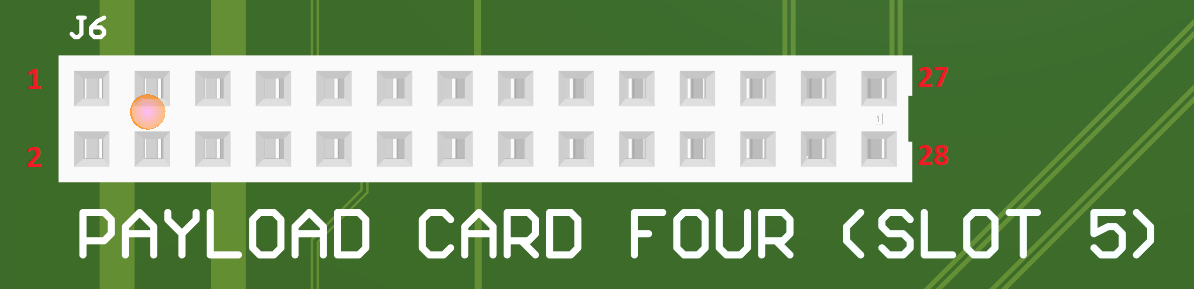
Payload Card Slot Four (Slot 5)
Molex Part #: 0791077013
| 1 | 3 | 5 | 7 | 9 | 11 | 13 | 15 | 17 | 19 | 21 | 23 | 25 | 27 |
| 2 | 4 | 6 | 8 | 10 | 12 | 14 | 16 | 18 | 20 | 22 | 24 | 26 | 28 |
Reference view for pinout of connector is from FRONT of card.
Pin Number
Pin Function
| Pin Number | Pin Function |
|---|---|
| 1 | 12V Power Rail |
| 2 | 12V Power Rail |
| 3 | Ground |
| 4 | Ground |
| 5 | 5V Power Rail |
| 6 | 5V Power Rail |
| 7 | Ground |
| 8 | Ground |
| 9 | CAN + |
| 10 | CAN - |
| 11 | Ground |
| 12 | Ground |
| 13 | GPIO - Common |
| 14 | GPIO - 10 |
| 15 | GPIO - 11 |
| 16 | GPIO - 12 |
| 17 | SPARE |
| 18 | SPARE |
| 19 | SPARE |
| 20 | SPARE |
| 21 | SPARE |
| 22 | SPARE |
| 23 | Ground |
| 24 | Ground |
| 25 | Ethernet Link 5 - TX+ |
| 26 | Ethernet Link 5 - TX- |
| 27 | Ethernet Link 5 - RX+ |
| 28 | Ethernet Link 5 - RX- |
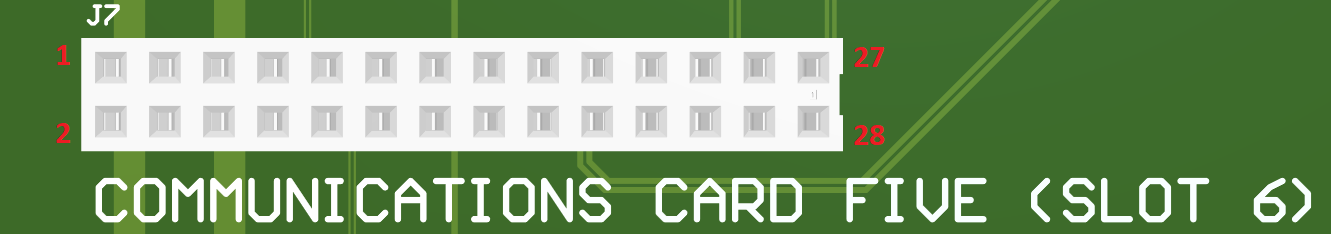
Communications Card Interface (Slot 6)
Molex Part #: 0791077013
| 1 | 3 | 5 | 7 | 9 | 11 | 13 | 15 | 17 | 19 | 21 | 23 | 25 | 27 |
| 2 | 4 | 6 | 8 | 10 | 12 | 14 | 16 | 18 | 20 | 22 | 24 | 26 | 28 |
Reference view for pinout of connector is from FRONT of card.
Pin Number
Pin Function
| Pin Number | Pin Function |
|---|---|
| 1 | 12V Power Rail |
| 2 | 12V Power Rail |
| 3 | Ground |
| 4 | Ground |
| 5 | 5V Power Rail |
| 6 | 5V Power Rail |
| 7 | Ground |
| 8 | Ground |
| 9 | CAN + |
| 10 | CAN - |
| 11 | Ground |
| 12 | Ground |
| 13 | GPIO - Common |
| 14 | GPIO - 13 |
| 15 | GPIO - 14 |
| 16 | GPIO - 15 |
| 17 | Ground |
| 18 | Ground |
| 19 | USB 2.0 - D- |
| 20 | USB 2.0 - D+ |
| 21 | SPARE |
| 22 | SPARE |
| 23 | Ground |
| 24 | Ground |
| 25 | Ethernet Link 6 - TX+ |
| 26 | Ethernet Link 6 - TX- |
| 27 | Ethernet Link 6 - RX+ |
| 28 | Ethernet Link 6 - RX- |
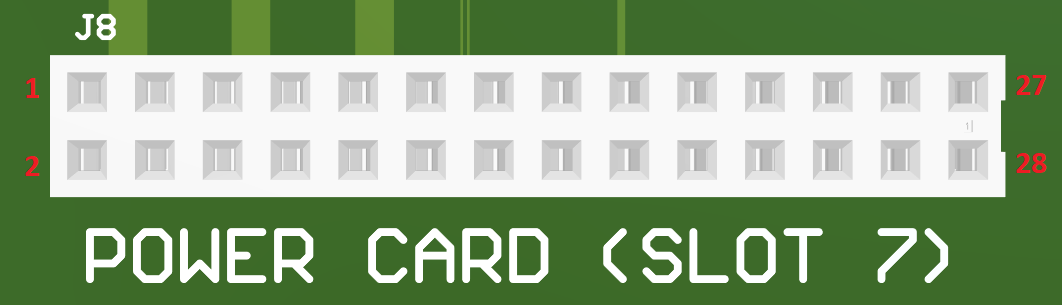
Power Supply Card (Slot 7)
Molex Part #: 0791077013
| 1 | 3 | 5 | 7 | 9 | 11 | 13 | 15 | 17 | 19 | 21 | 23 | 25 | 27 |
| 2 | 4 | 6 | 8 | 10 | 12 | 14 | 16 | 18 | 20 | 22 | 24 | 26 | 28 |
Reference view for pinout of connector is from FRONT of card.
Pin Number
Pin Function
| Pin Number | Pin Function |
|---|---|
| 1 | Shore Power Input |
| 2 | Shore Power Input |
| 3 | Ground |
| 4 | Ground |
| 5 | 12V Power Rail |
| 6 | 12V Power Rail |
| 7 | Ground |
| 8 | Ground |
| 9 | 5V Power Rail |
| 10 | 5V Power Rail |
| 11 | Ground |
| 12 | Ground |
| 13 | CAN + |
| 14 | CAN - |
| 15 | Ground |
| 16 | Ground |
| 17 | GPIO - Common |
| 18 | GPIO - 16 |
| 19 | GPIO - 17 |
| 20 | GPIO - 18 |
| 21 | SPARE |
| 22 | SPARE |
| 23 | SPARE |
| 24 | SPARE |
| 25 | SPARE |
| 26 | SPARE |
| 27 | SPARE |
| 28 | SPARE |
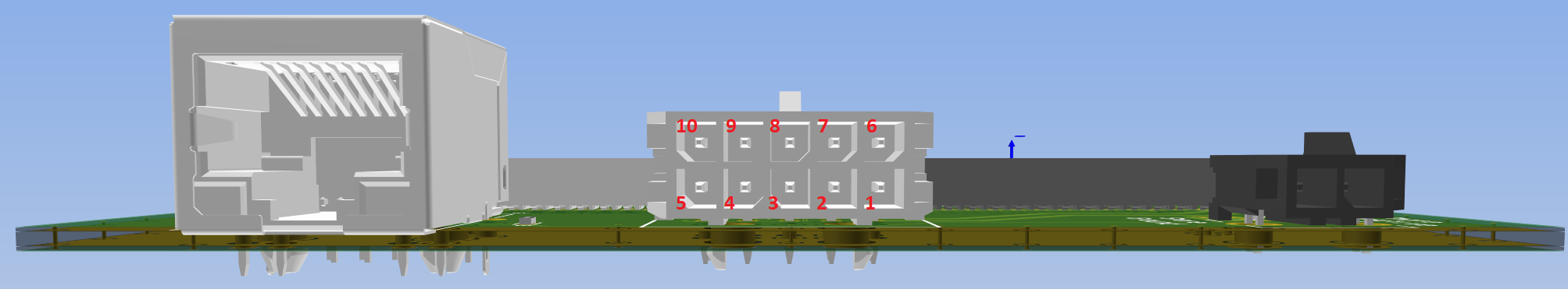
Balloon Board
Molex Part #: 0430451000
| 10 | 9 | 8 | 7 | 6 |
| 5 | 4 | 3 | 2 | 1 |
Reference view for pinout of connector is from top edge of board looking towards connector.
Pin Number
Pin Function
| Pin Number | Pin Function |
|---|---|
| 1 | 12V Power Rail |
| 2 | Ground |
| 3 | Ground |
| 4 | GPIO-1 (connected to MFC - GPIO-19) |
| 5 | CAN - |
| 6 | 5V Power Rail |
| 7 | Ground |
| 8 | GPIO - Common |
| 9 | GPIO-2 (connected to MFC - GPIO-20) |
| 10 | CAN + |